|
|
||
|
|
 |
|
|
|
||
|
|
||
|
|
Building a Light Box for a 4 Inch Refractor |
|
|
|
||
|
|
||
|
|
Click the thumbnails to show the full images
Weather Data
|
|
|
|
||
|
|
|
|||
|
|
Light Box Construction for a TeleVue NP101 4 inch Refractor By Michael R Turner I will not rehash the necessity of taking flat frames to cleanup CCD images. There are many articles scattered around the internet that provide a very in depth discussion of this topic. My preference is Ron Wodaski's The New CCD Astronomy, Chapter 6, Increasing Image Quality (http://www.newastro.com). The construction is based on the ideas from Dean Salmon (http://galaxies.com/ccdinfo/LightBox.aspx) and the 5k Ohm pot from Don Goldman (http://astrodon.com/LearningCurve.html). I added my own modification of the tube supports so that the Light Box would be free-standing on the telescope. Parts List 1. 1 sheet of X-Acto Foam Board - 5 mm thick. 2. 4 White LEDs Radio Shack 276-320 (D1 - D4) 3. 4 LED Panel Mounts Radio Shack 276-080 4. 1 5K Ohm Linear Taper Pot Radio Shack 271-1714 (R2) 5. 1 Knurled Knob Radio Shack 274-424 (for pot) 6. 1 100 Ohm 1/4 watt resistor (from resistor kit) (R1) 7. 2.5 mm monaural audio jack (12vdc receptacle) (J1) 8. 185 cm cord with 2.5 mm monaural stereo plug installed (12vdc feed) 9. 2 sheets of Translucent Alabaster velum paper 10 Hold-The-Foam Foam Board glue. Tools 1. X-Acto knife 2. Dremel Tool with Saw Blade cutting Wheel 3. Steel Ruler 455 mm 4. Hot glue gun with clear glue 5. Soldering iron 6. Hand tools 7. Glue stick
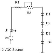
The Circuit Design
The LEDs are white LEDs that are formed by doping a blue LED with yellow phosphor. They are rated at 3.6 vdc forward voltage at 20 ma with 1100 mcd luminous intensity. The viewing angle is approximately 100 degrees at the 50 percent viewing points on either side of center. I chose the panel mounts to simplify recovering the LEDs if I decide to change the design. The circuit design and the LEDs were tested to insure that they would provide the proper brightness for the flat fields for the refractor and the ST2000XM camera. Power is provided via a 2.5 mm monaural audio jack (12vdc receptacle) installed in my main power pack (battery case).
1. LED circuit 2. Testing the LEDs
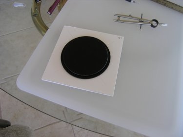
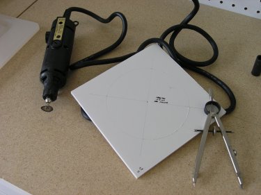
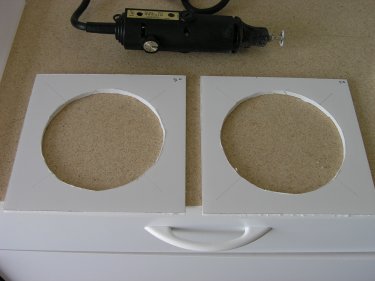
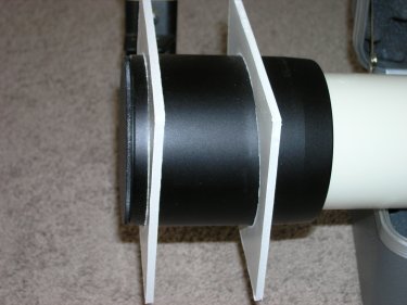
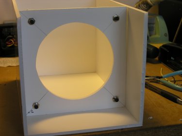
Getting Started I chose the 5 mm foam board because I have experience working with this material (good old story boards from marketing class). Using the proper techniques can result in precise cuts and clean edges. It is very light weight, and structurally sound, once glued together. The main design modification was to add an additional 67 mm to the rear of the light box and include a second circular tube support so that the box would be self-standing on the telescope. The basic box is 280 mm by 175 mm by 175 mm. Using Dean's formula of 2 times the objective diameter for the length of the box, the interior of the box is 202 mm by 165 mm. I cut three 165 mm square pieces using an X-Acto knife for the front piece and the two internal supports, two 175 mm by 280 mm pieces for the top and bottom, and two 165 mm by 280 mm pieces for the sides. The NP101 has a built-in dew shield with an outside diameter of 125 mm, but also has a tapered nose. Using the lens cap from the refractor as a template, I cut a 122 mm hole in one support and a 126 mm hole in the rear support using the Dremel tool with the circular saw blade.
3. Tube support template 4. Cutting tube supports
The tube supports were dry fitted to the scope and minor adjustments were made.
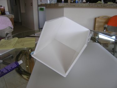
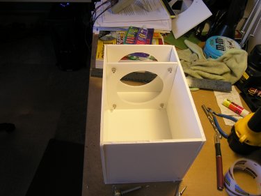
5. Tube supports 6. Checking tube support fit Construction I glued the two 165 mm by 280 mm side pieces to the front 165 mm square piece using the Hold-The-Foam glue. This glue has a 15 second initial setup time, but also allows you to readjust the pieces before it fully cures in about 2 minutes. The Hold-The-Foam glue is available at many Art’s and Craft’s stores. I glued one of the 175 mm by 280 mm pieces to the sides and front to form the bottom of the box.
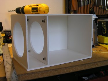
7. Basic Box 8. Box with Tube Supports
Mounting and Wiring The LEDs
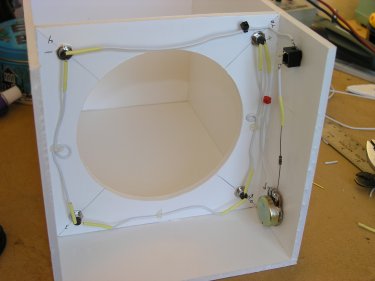
The internal support with the 122 mm hole is used for the LED holder. Using the centering guide marks left over from the laying out the circles, I marked and drilled 4 – 6 mm holes 32 mm from the edge of the circle for the LED mounts. The nuts for the LED mounts just fit the 5 mm thickness of the Foam Board if the lock washer is removed.
9. LEDs Mounted - Rear View 10. LEDs Mounted - Front View
The LEDs are wired in series, with a 100 Ohm fixed current limiting resistor and a 5,000 Ohm linear taper potentiometer, to allow adjusting the brightness of the LEDs, also in series on the positive supply side. The LEDs are “bare”. They do not have a diffusing cover. The 12vdc power receptacle and the 5K Ohm pot are mounted in the Foam Board using the hardware that came with the items. The knurled knob was mounted on the shortened 5K Ohm pot shaft and secured with its set screw.
11. LED Wiring 12. Basic Box with Internal Tube Supports
The internal tube support, with the LEDs, was glued in place 101 mm from the inside of the front of the box. I made two measurement marks on each side of the box 106 mm from the front to insure that the support was straight. I was careful not to make any marks on the inside of the main light box. Next, the outer tube support with the 126 mm hole was glued in place at the rear of the box.
Finishing the Construction
At this point, I did a dry fit of the box on the telescope to verify that all of the parts cleared the tube and that the internal support fit the tapered dew shield nose properly. It fits approximated half way up the taper. The velum paper was then glued in on all sides. This paper eliminates the harsh reflections caused by the glossy Foam Board and the shadows created by the bare LEDs. The result is well mixed and diffused light. Finally, the top was glued to the box. This was probably the hardest piece to get squared. Fortunately, the care measuring and cutting the other pieces was worth the effort.
First Light (pun intended)
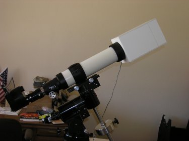
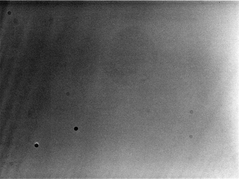
The 12 vdc power cord was made from an old wall power pack cable and a 2.5 mm monaural audio plug. The 185 cm power cord provides enough cable to fit any angle that the mount may slew the scope to. I do not leave the cable connected while the mount is slewing. I turned on the computer, turned on the ST2000XM and verified that they were working. The light box was turned on and CCDOPS was used in the Focus mode to adjust the brightness of the LEDs to approximately 30,000 units, which is about 67 percent of the full well capacity of the ST2000XM. Several flats were taken and analyzed to “see” what the optical system looked like.
13. First Light 14. Initial Flat Frame
Finishing the Light Box
The prototype of the box works well. There are several light leaks that must be fixed, where the glue did not completely seal the gaps. Also, an outer covering needs to be installed to shield the box. It looks like a big orange flame stuck on the end of the telescope.
Conclusion
Building the light box was fun and educational. Future modifications include modifying the LED circuit to wire the LEDs in parallel to provide a finer range of brightness adjustment. And, change the LED mounts to use a diffuser over the LEDs.
|
|||
|
|
||||